| Additional Information: | 2023:
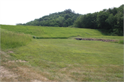
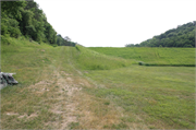
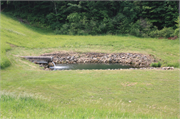
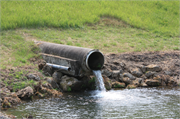
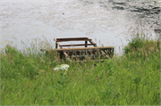
West Fork Kickapoo 12 was constructed in 1964 on an unnamed tributary of the West Fork Kickapoo east of Bloomingdale Road. It is an earthen fill dry dam with an emergency spillway at the north abutting end. The principal spillway is a reinforced concrete pressure pipe conduit laid in a cast concrete cradle with flanking seepage relief pipes. The spillway conduit is cantilevered above a rip rap lined stilling basin. The dam has a two-stage inlet consisting of a low stage drain inlet and a one-stage open top, drop inlet riser at the base of the east facing upstream slope.
The West Fork Kickapoo Watershed includes nine earthen dams constructed under the National Resource Conservation Watershed Authority between 1956 and 1971 consisting of West Fork Kickapoo Pilot Klinkner (245824), West Fork Kickapoo Pilot Mlsna (245825), West Fork Kickapoo 1 (245827), West Fork Kickapoo 3 (245831), West Fork Kickapoo 4 (245832), West Fork Kickapoo 5 (245833), West Fork Kickapoo 12 (245828), West Fork Kickapoo 16 (245829), and West Fork Kickapoo 17 (245830). Two dams, Pilot Klinkner (245824) and Pilot Mlsna (245825) were constructed under the Pilot Watershed Program (PL-156). The other seven dams were designed and evaluated under the Work Plan for Watershed Protection and Flood Prevention, West Fork Kickapoo Watershed, Monroe and Vernon Counties, Wisconsin (1961, as amended) and were constructed under the Watershed Protection and Flood Prevention Act of 1954 (PL-566). Generally, the dams are similarly engineered with variations appropriate to the conditions of each site and constructed with a 50-year service life. Of these, West Fork Kickapoo 1 (245827) is the only multipurposed dam for flood retention and recreation, whereas the other eight dams are single purpose flood retention dams.
Each dam is an earthen embankment of compacted natural soil and rock fill materials consisting of a select material core, predominantly clay, that is compacted to eliminate seepage. The core is surrounded by a fill material shell with a wide, flat crest and sodded valleys at abutting ends. Fill material was sourced from borrow areas on site or in the near vicinity. Below the embankment, a foundation trench drain is located near the downstream toe of the dam to intercept any water that may seep through the foundation soils or rock. Stability berms may be constructed along the downstream slope based on force resistance and anticipated seepage rates.
Most dams in the West Fork Kickapoo Watershed are of the dry-dam type impounding water and sediment temporarily during heavy rain events and slowly releasing the impoundment to prevent inundation downstream. However, several of the dams were constructed to create permanent sediment pools based on property owner preference.
All nine dams were constructed with principal spillways. These are straight, reinforced concrete conduits that run perpendicular to the base of the dam. The conduits are either reinforced concrete pressure pipes or cast-in-place rectangular reinforced concrete conduits. Conduit size and type vary based on the anticipated annual impoundment volume and velocity of the outflow. Smaller pipes on either side of the conduit run lengthwise along the interior of the dam to collect seepage and spring water. Most, but not all dams, also have auxiliary emergency spillways. These are earthen vegetated (grass) open channels constructed at an abutting end perpendicular to the dam and generally consist of an inlet channel, a control section, and an exit channel. The auxiliary spillways are designed on the basis that some erosion or scour will occur during passage of infrequent storms, but the spillway should not breach during passage of base level or freeboard storm.
The principal spillways have multiple-stage inlets at two or more elevations. Generally, in the project area, dams with auxiliary spillways have two stage inlets whereas dams without auxiliary spillways have three stage risers that are tall and tower-like. The original watershed work plans also indicate that the type of riser may be dependent on the level hazard at each site, i.e. one stage risers for lower hazard sites and two-stage risers for higher hazard sites. The lower stage or stages are intended to perform the primary flood control function, and the high stage is to prevent the auxiliary spillway from functioning more frequently than permissible during high rain events. For the dry dams, the lowest stage inlet is a ground level drain placed at the submerged sediment pool elevation such that the temporary impoundment is drained in a reasonable amount of time. For the permanent impoundments, placement of the low stage inlet is dependent upon the capacity and depth of the planned sediment storage. The mid- or high stage inlet is an open top, drop inlet riser that varies in height depending on the number of stages, the anticipated flood water level, and the impoundment type. Both connect to the principal spillway via draw down pipes. Trash racks are installed at the opening of the risers to prevent objects too large to pass freely through the spillway from entering the inlet. Water conveyed via the principal spillway is deposited in a downstream stilling basin or plunge pool to dissipate energy before entering the outlet channel.
|
|---|

